CAPACITORS AND CAPACITANCE
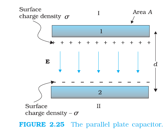
`color{blue} ✍️` A capacitor is a system of two conductors separated by an insulator (Fig. 2.24).
`color{blue} ✍️` The conductors have charges, say `Q_1` and `Q_2,` and potentials `V_1` and `V_2`. Usually, in practice, the two conductors have charges `Q` and `– Q,` with potential difference `V = V_1 – V_2` between them.
`color{blue} ✍️` We shall consider only this kind of charge configuration of the capacitor. (Even a single conductor can be used as a capacitor by assuming the other at infinity.)
`color{blue} ✍️` The conductors may be so charged by connecting them to the two terminals of a battery. `Q` is called the charge of the capacitor, though this, in fact, is the charge on one of the conductors – the total charge of the capacitor is zero.
`color{blue} ✍️` The electric field in the region between the conductors is proportional to the charge `Q.` That is, if the charge on the capacitor is, say doubled, the electric field will also be doubled at every point. (This follows from the direct proportionality between field and charge implied by Coulomb’s law and the superposition principle.)
`color{blue} ✍️` Now, potential difference `V` is the work done per unit positive charge in taking a small test charge from the conductor 2 to 1 against the field. Consequently, `V` is also proportional to `Q,` and the ratio `Q/V` is a constant:
`color{blue} ✍️` The constant `C` is called the capacitance of the capacitor. `C` is independent of `Q` or `V,` as stated above.
`color{blue} ✍️` The capacitance `C` depends only on the geometrical configuration (shape, size, separation) of the system of two conductors. [As we shall see later, it also depends on the nature of the insulator (dielectric) separating the two conductors.]
`color{blue} ✍️` The SI unit of capacitance is 1 farad `(=1 "coulomb volt"^(-1)) or 1 F = 1 C V^(–1)`.
`color{blue} ✍️` A capacitor with fixed capacitance is symbolically shown as
`color{blue} ✍️` Equation (2.38) shows that for large `C, V` is small for a given `Q`. This means a capacitor with large capacitance can hold large amount of charge `Q` at a relatively small `V`.
`color{blue} ✍️` This is of practical importance. High potential difference implies strong electric field around the conductors.
`color{blue} ✍️` A strong electric field can ionise the surrounding air and accelerate the charges so produced to the oppositely charged plates, thereby neutralising the charge on the capacitor plates, at least partly.
`color{blue} ✍️` The maximum electric field that a dielectric medium can withstand without break-down (of its insulating property) is called its dielectric strength; for air it is about `color{purple}(3 × 10^6 Vm^(–1.))`
`color{blue} ✍️` For a separation between conductors of the order of `1 cm` or so, this field corresponds to a potential difference of `color{purple}3 × 10^4 V` between the conductors.
`color{blue} ✍️` Thus, for a capacitor to store a large amount of charge without leaking, its capacitance should be high enough so that the potential difference and hence the electric field do not exceed the break-down limits.
`color{blue} ✍️` Put differently, there is a limit to the amount of charge that can be stored on a given capacitor without significant leaking. In practice, a farad is a very big unit; the most common units are its sub-multiples `color{purple}(μF = 10^(–6) F, 1 nF = 10^(–9) F, 1 pF = 10^(–12) F,)` etc.
`color{blue} ✍️`Besides its use in storing charge, a capacitor is a key element of most ac circuits with important functions, as described in Chapter 7.
`color{blue} ✍️` The conductors have charges, say `Q_1` and `Q_2,` and potentials `V_1` and `V_2`. Usually, in practice, the two conductors have charges `Q` and `– Q,` with potential difference `V = V_1 – V_2` between them.
`color{blue} ✍️` We shall consider only this kind of charge configuration of the capacitor. (Even a single conductor can be used as a capacitor by assuming the other at infinity.)
`color{blue} ✍️` The conductors may be so charged by connecting them to the two terminals of a battery. `Q` is called the charge of the capacitor, though this, in fact, is the charge on one of the conductors – the total charge of the capacitor is zero.
`color{blue} ✍️` The electric field in the region between the conductors is proportional to the charge `Q.` That is, if the charge on the capacitor is, say doubled, the electric field will also be doubled at every point. (This follows from the direct proportionality between field and charge implied by Coulomb’s law and the superposition principle.)
`color{blue} ✍️` Now, potential difference `V` is the work done per unit positive charge in taking a small test charge from the conductor 2 to 1 against the field. Consequently, `V` is also proportional to `Q,` and the ratio `Q/V` is a constant:
`bb (C = Q/V)`
.................2.38`color{blue} ✍️` The constant `C` is called the capacitance of the capacitor. `C` is independent of `Q` or `V,` as stated above.
`color{blue} ✍️` The capacitance `C` depends only on the geometrical configuration (shape, size, separation) of the system of two conductors. [As we shall see later, it also depends on the nature of the insulator (dielectric) separating the two conductors.]
`color{blue} ✍️` The SI unit of capacitance is 1 farad `(=1 "coulomb volt"^(-1)) or 1 F = 1 C V^(–1)`.
`color{blue} ✍️` A capacitor with fixed capacitance is symbolically shown as
`color{blue} ✍️` Equation (2.38) shows that for large `C, V` is small for a given `Q`. This means a capacitor with large capacitance can hold large amount of charge `Q` at a relatively small `V`.
`color{blue} ✍️` This is of practical importance. High potential difference implies strong electric field around the conductors.
`color{blue} ✍️` A strong electric field can ionise the surrounding air and accelerate the charges so produced to the oppositely charged plates, thereby neutralising the charge on the capacitor plates, at least partly.
`color{blue} ✍️` The maximum electric field that a dielectric medium can withstand without break-down (of its insulating property) is called its dielectric strength; for air it is about `color{purple}(3 × 10^6 Vm^(–1.))`
`color{blue} ✍️` For a separation between conductors of the order of `1 cm` or so, this field corresponds to a potential difference of `color{purple}3 × 10^4 V` between the conductors.
`color{blue} ✍️` Thus, for a capacitor to store a large amount of charge without leaking, its capacitance should be high enough so that the potential difference and hence the electric field do not exceed the break-down limits.
`color{blue} ✍️` Put differently, there is a limit to the amount of charge that can be stored on a given capacitor without significant leaking. In practice, a farad is a very big unit; the most common units are its sub-multiples `color{purple}(μF = 10^(–6) F, 1 nF = 10^(–9) F, 1 pF = 10^(–12) F,)` etc.
`color{blue} ✍️`Besides its use in storing charge, a capacitor is a key element of most ac circuits with important functions, as described in Chapter 7.